


What is Spanning Tree Protocol (STP)
Most of the people that work with network equipment know for having more band width in network must connect switches and routers together. When you do it, will make redundancy in network and finally it causes the loop. STP is enabled as default and prevented to make loop.
For getting better the function of network equipment and improvement the Performance of network, provided a lot of protocols that we explained some of them in Atech blog. In this article, we want to talk about STP protocol. What is it? Different types of it and more. Spanning Tree Protocol is a layer2 protocol that used to prevent looping within network topology.
What is Spanning Tree Protocol (STP)?
As we said, STP is a layer2 protocol that was created to avoid the problems that arise when computers exchange data on a local area network (LAN) that contains redundant paths. If the flow of traffic is not carefully monitored and controlled, the data can be caught in a loop that circles around network segments, affecting performance and bringing traffic to a near halt.
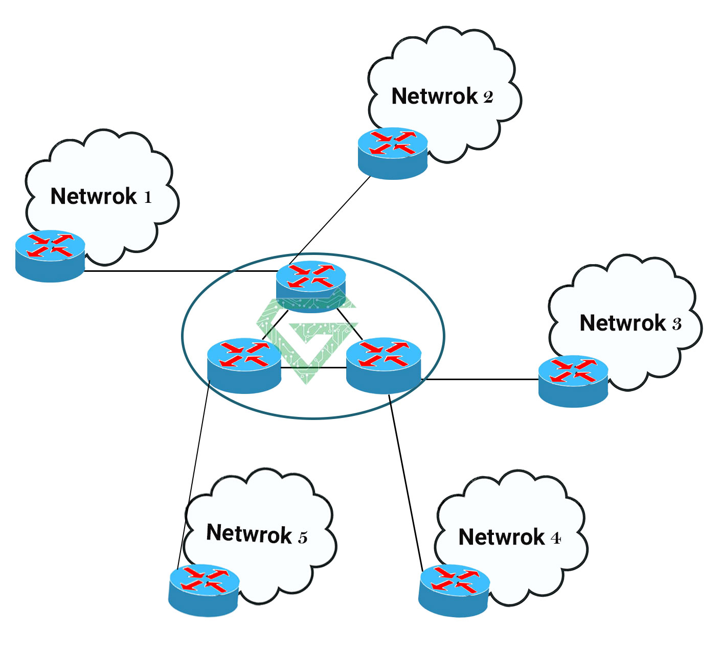
Networks are often configured with redundant paths when connecting network segments. Although redundancy can help protect against disaster, it can also lead to bridge or switch looping. Looping occurs when data travels from a source to a destination along redundant paths and the data begins to circle around the same paths, becoming amplified and resulting in a broadcast storm.
STP can help prevent bridge looping on LANs that include redundant links. Without STP, it would be difficult to implement that redundancy and still avoid network looping. STP monitors all network links, identifies redundant connections and disables the ports that can lead to looping.
Totally, the basic function of Spanning Tree Protocol is to prevent bridge loops and the broadcast radiation that results from them. Spanning tree also allows a network design to include backup links providing fault tolerance if an active link fails.
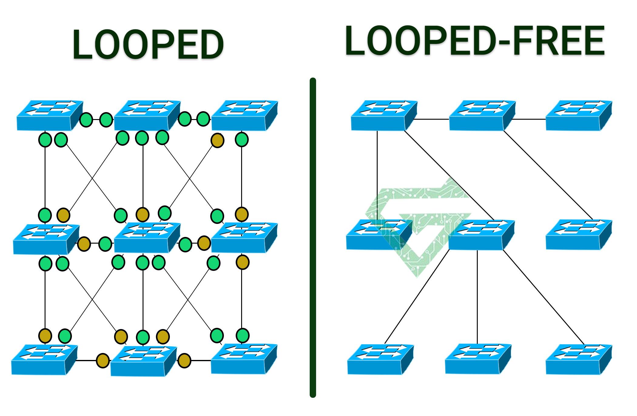
As the name suggests, STP creates a spanning tree that characterizes the relationship of nodes within a network of connected layer-2 bridges, and disables those links that are not part of the spanning tree, leaving a single active path between any two network nodes.
LANs are often divided into multiple network segments, and they use bridges to connect the individual segment pairs. Each message, called a frame, goes through the bridge before being sent to the intended destination.
The bridge determines whether the message is for a destination within the same segment as the sender’s or for another segment and then forwards the message accordingly. When used in the context of STP, the term bridge can also refer to a network switch.
A bridge looks at the destination address and, based on its understanding of which computers are on which segments, forwards the data on the right path via the correct outgoing port.
Network segmentation and bridging can reduce the amount of competition for a network path by half assuming each segment has the same number of computers. As a result, the network is much less likely to come to a halt.
A segmented LAN is often designed with redundant bridges and paths to ensure that communications can continue in the event that a network link becomes unavailable. However, this makes the network more susceptible to looping, so a system must be put into place to prevent this possibility, which is where STP comes in.
Read more: What is Cisco Switch
What are different types of Spanning Tree Protocol:
The STP protocol suite includes several types of protocols, each designed with specific goals and features. Some of the types of STP are:
- Standard STP: This type of STP is the most basic version of the Spanning Tree Protocol and used to prevent loops in the network. In this type of STP, by default, all switches are considered active switches (non-root bridges) and perform tree scanning using BPDU messages.
- RSTP: This type of STP operates faster and with lower response time than standard STP. In RSTP, each switch is designated as an active switch (active bridge) or a passive switch (backup bridge). Active switches participate in tree scanning, and in the event of an error in tree scanning, passive switches become active switches.
- MSTP: This type of STP is used to prevent loops in networks with different VLANs (virtual local area networks). In MSTP, the network is divided into several areas and in each area a dedicated tree is created for the VLANs associated with that area. This type of Spanning Tree Protocol uses tree scanning algorithms to obtain the shortest path distance between devices and selects the best path for communication between devices. In general, the use of each type of STP is determined depending on the needs and characteristics of the networks in question.
- Per-VLAN Spanning Tree (PVST):PVST is a Cisco-proprietary protocol that creates a separate spanning tree for each VLAN. This allows network administrators to configure and manage each VLAN independently, offering more control and flexibility. It has further extensions some text.
- Per-VLAN Spanning Tree Plus (PVST+):PVST+ extends PVST capabilities by adding support for the IEEE 802.1Q standard, enabling interoperability with non-Cisco devices.
- Rapid PVST+ (RPVST+):RPVST+ is an extension of PVST+ that incorporates the rapid convergence benefits of RSTP. It provides per-VLAN rapid spanning tree instances, combining the best features of both RSTP and PVST+.
Spanning Tree Protocol port states:
There are some states for ports of STP. When Spanning Tree Protocol is enabled on a network bridge, each port is set to one of five states to control frame forwarding:
- Disabled: This port of STP does not participate in frame forwarding or STP operations. In the STP protocol, this port mode is off.
- Blocking: This port of STP does not participate in frame forwarding and discards frames received from the attached network segment. However, the port continues to listen for and process BPDUs.
- Listening: from the blocking state, the port transitions to the listening state. The port discard frames from the attacked network segment or forwarded from another port. However, it receives BPDUs and redirects them to the switch module for processing.
- Learning: This port moves from the listening state to the learning state. It listens for and processes BPDUs but discards frames from the attached network segment or forwarded from another port. It also starts updating the address table with the information it’s learned. In addition, it processes user frame but does not forward those frames.
- Forwarding: this port moves from the learning state to the forwarding state and states forwarding frames across the network segments. This includes frames from the attached network segment and those forwarded from another port. The port also continues to receive and process BPDUs, and the address table continues to be updated.
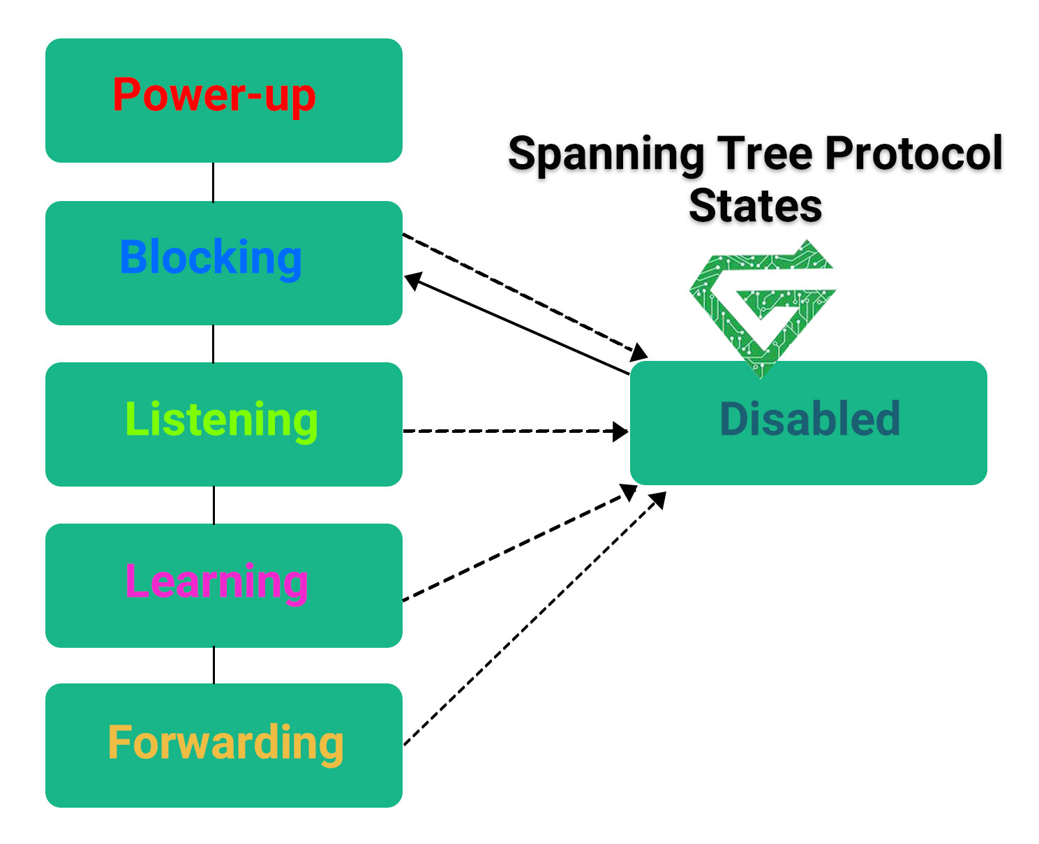
STP moves from the blocking state through the forwarding state in relatively short order, usually between 15 to 20 seconds for each state. Every port starts in the blocking state. If it has been disabled, the port enters directly into the blocking state upon being enabled. Spanning Tree Protocol balances the states across ports to avoid bridge looping, while still making redundancy possible.
Is STP used in all networks:
The answer is yes, the STP (Spanning Tree Protocol) is a standard protocol at the second layer of the OSI (Data Link Layer) model that is used to prevent loops in the network and establish a communication tree in the network. This protocol is defined by the IEEE (Institute of Electrical and Electronics Engineers) and is implemented in all networks that use the Ethernet protocol.
Therefore, STP is implemented in all networks that use the Ethernet protocol and is used to prevent loops in the network and improve network performance and reliability. However, some networks may use other protocols to prevent loops in the network, but STP is widely used as a standard protocol in computer networks.
Read more: What is MAC address
What are the features of STP?
- Preventing loops in the network: The STP protocol prevents loops in the network by creating a communication tree in the network. With this method, all devices in the network communicate seamlessly and enjoy higher efficiency.
- Tree scanning: STP uses tree scanning algorithms to select the best path between devices for communication between them. These algorithms select the optimal communication path between devices based on the shortest path distance to the root of the tree.
- Path replacement: If a link in the network is disconnected, Spanning Tree Protocol automatically selects an alternative path using other links and prevents network outages.
- Root switch selection: STP forms a communication tree by selecting one of the switches as the root switch. Other switches automatically select the best path to the root.
- Configurable: STP is configurable and can be dynamically adjusted based on network needs. For example, you can change the number of tree scans or adjust the delay time between tree scans. Overall, STP creates a sense of network standardization by preventing loops in the network and helps improve network efficiency by optimizing the communication path between devices.
What is STP steps:
For performing STP and for making a network without Loop, you need to do these steps;
- Choosing a Root Bridge:
The main point and root where Spanning Tree Protocol (STP) calculations are made is the Root Bridge, where only one switch in a VLAN can be the Root. The Root Bridge has the smallest Bridge ID or BID at the network level, and whenever a switch with a smaller BID is connected to the network, it becomes the Root Bridge and the calculations are resumed.
As a result, the looped links that are relatively far from the Root Bridge will be blocked, and the network view from the new root or Root is formed, and distances and costs are calculated relative to that point. The Root Bridge advertises itself in the network every two seconds. The Configuration BPDU contains Spanning Tree information, which is distributed only by the Root Bridge in the network every two seconds.
Initially, all the switches in the network see themselves as the Root Bridge and start advertising themselves until a Configuration BPDU from a better BID (better priority means lower or in case of equal priority, smaller Mac Address) is received.
To elect the Root Bridge, each switch first creates a BPDU packet containing its own Bridge ID and sends it to everyone. If the switch receives a Superior Hello, it drops its claim and starts sending that Superior Hello. Eventually, all switches except the switch with the smallest Bridge ID stop generating and that switch is elected as the Root Switch and generates and sends BPDUs, and the rest of the switches only receive and send them.
In the 802.ID standard, the Bridge ID consisted of two fields: Priority and MAC Address, but this format was changed and the Priority field was divided into two fields: Priority and extension system ID, which is the VLAN ID.
- Choosing Root port:
Once the Root Bridge is selected, the other switches need to designate a port as the Root Port, or in other words, the other switches will see it through one of their ports. To do this, follow these steps:
- The Root Switch creates and sends Hello Timer Default with Cost=0 every 2 seconds.
- Each switch sends it after receiving the BPDU and making changes to the following fields: Cost Forwarding Switch’s Bridge ID Forwarder’s Port Priority Forwarder’s Port Number
- Switches do not send BPDUs on ports that have gone into Blocking mode.
- Among all the ports of a switch, the port that receives the BPDU with the lowest Cost is selected as the RP.
To calculate the cost until reaching the Root Switch, the switches add the Cost value in the received BPDU with the Cost of the port with which they received the BPDU and obtain the new Cost value of the switch up to the Root Bridge and send it to the other switches.
- Choosing Designated Port:
If two or more switches are connected to a segment in a LAN, only one switch should receive and send segment frames. This is done to prevent loops. The port that connects the segment to the LAN is called the Designated Port. This switch has the best Root Path Cost and if equal conditions are met, the selection is made based on the four main criteria mentioned earlier.
How to configure STP protocol?
There are different ways for configuration. Such as CLI, GUI and management network protocols.
- CLI (Command-Line Interface): This is a very common method for configuring Spanning Tree Protocol, and many switches support this feature. Using the CLI, you can configure STP settings manually using commands. For example, to configure the STP origin, you can use the set span tree root primary command.
- GUI (Graphical User Interface): Many switches have a graphical user interface through which you can configure STP. In this method, the user uses the mouse and keyboard to configure the desired settings.
- Network management protocols: Many network management protocols including SNMP (Simple Network Management Protocol), Telnet, and SSH, support STP configuration. Using these protocols, you can change STP settings remotely from anywhere. Depending on the type of switch and the software used, there are other methods for configuring STP. Also, to configure Spanning Tree Protocol, you need to be familiar with concepts like root switch, root ports, blocked ports, etc. So, before configuring STP, it is better to familiarize yourself with its basic concepts and then proceed to configure it.